


How can quick and easy measurements with the GS18 I be so accurate?

The Leica GS18 I is a versatile and easy to use GNSS rover that uses Visual Positioning technology to measure points remotely in images. The system integrates a GNSS sensor with an IMU and a camera. Due to its precisest sensor fusion, it is possible to measure inaccessible points in images right away in the field. I explained in Q&A on Visual Positioning and Leica GS18 I how the GS18 I captures and processes images. With this expert insight, we will take it one step further. I will describe some fundamentals of photogrammetry and take a closer look at the automated matching process that allows measuring of survey-grade points in images in Leica Captivate.
How is it possible to measure points by selecting only one point in an image?
Immediately after capturing an image group, Captivate processes the GS18 I data and computes the position and orientation of each image. Therefore, the user can select one image, click on one point in it, press Measure and “Voilà!” – 3D point coordinates have already been calculated in a global coordinate system. As you can see, the workflow of measuring points in images is effortless and straightforward. This is possible thanks to the highly precise and reliable point matching algorithm running on Captivate (often referred to as AR tracking).
This seems relatively straightforward. But have you ever asked yourself how exactly the points are matched? To answer this question, I’ll first explain some fundamentals of photogrammetry.
Photogrammetry is the science of making measurements from images. The position of one point can be reconstructed from images that are positioned and oriented in a local coordinate system. The position of one object point can be defined by intersecting bundles of image rays, like in Figure 1.
Figure 1: Intersecting bundles of image rays

To be more specific, an image ray starts at a perspective centre of the camera, passes through the marked image point and goes to infinity, just like in Figure 2.
Figure 2: A perspective centre and an image ray

The object point we want to measure can be at any point along that image ray. To calculate the exact position of that point, at least two spatially separated image rays that intersect at one point are needed. These two rays must be defined by two different images. By increasing the number of image rays used for the reconstruction, the position accuracy will improve.
To define the direction of the image rays, users typically have to mark the point in each image manually. This is not needed when using images captured with the GS18 I. The following video nicely animates each step of the point matching algorithm, demonstrating how it automatically matches the marked point in the other captured images.
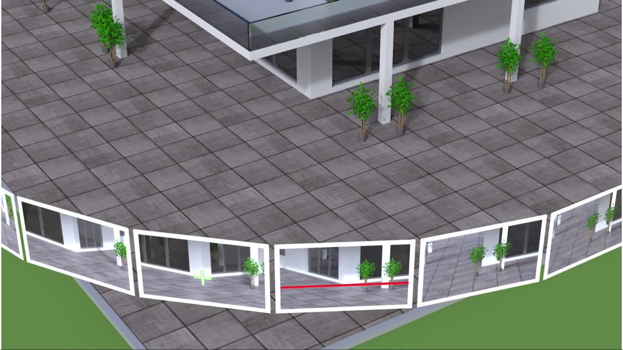
As shown in the animation, by marking one point in a selected image, the corresponding image ray will be computed. To define the direction of the second image ray, the same point has to be marked in the second image. The point matching algorithm does this automatically by connecting both perspective centres with a baseline. Now, using both the baseline and the first image ray, it is possible to create a plane. This plane is a so-called epipolar plane, and it intersects the second image along the red line called the epipolar line.
The epipolar line is crucial for the point matching algorithm because the point selected in the first image is located somewhere along the epipolar line in the second image. Therefore, the algorithm searches for the best match only along that line. First, Captivate defines a template matrix, a 19 x 19 matrix of greyscale pixels that surround the marked point of the first image. In the animation, the template matrix is framed by a green colour. In the second image, the algorithm detects in which segment of the epipolar line the point is located and makes a matrix scan only along this segment. By doing so, the processing time is reduced. During the scan, the algorithm extracts a 19 x 19-pixel matrix for each point along the selected part of the epipolar line.
In the next step, the algorithm searches for the best template match. Therefore, each of the matrices extracted from the second image are compared to the template matrix of the first image. This is done by calculating the correlations between the matrices. The extracted matrix with the highest correlation to the template is taken as the best match. Captivate then uses the surrounding pixels of this matrix to find the exact location of the point with sub-pixel accuracy. Captivate visualises this matched point with the blue symbol, and it appears in all images where the point was matched.
How smart is the point matching algorithm?
When developing the point matching algorithm, the aim was to create an algorithm that is as good at matching as the human visual sense is. However, it is clear that artificial and human intelligence cannot work in exactly the same way. For example, in many use cases, the point matching algorithm easily matches a point that could not be matched by the user. Look at the example in Figure 3.
Figure 3: Point marked in one image (left) and matched in another image (right)

On the left screen of Figure 3, one point on the pipeline is selected in the image. On the right screen, the same point is automatically matched in another image of the image group. One GS18 I user asked an excellent question: “How is it possible to automatically match the marked point in other images? Every point along this pipeline looks exactly the same to me, and I cannot see one unique point on this pipeline that I could manually match in two images. So, how can the algorithm do this if I cannot?”
The answer is quite simple. As I explained earlier, when a point is marked in one image, the matching algorithm first creates an epipolar line for each image. Then the algorithm searches along the epipolar line for the best match of the point. As shown in Figure 4, the epipolar line intersects the red line on the pipeline, and at the intersection point, the best match is found. And that is how it is easy for the algorithm to match the point in two images that the human eye could not distinguish.
Figure 4: Epipolar line

Sensor fusion, photogrammetry and cross-functional development to solve surveyors’ problems
The Visual Positioning technology is using photogrammetric principles for remote point measurement. In addition, sensor fusion gives GS18 I the ability to join GNSS and IMU data together with the captured images. The unique combination of both photogrammetry and sensor fusion simplifies the traditional photogrammetric workflow. What is more, the point matching algorithm speeds up the measurement process, and it even helps users measure points that cannot be matched manually in images. This way, users can easily measure points in images with survey-grade accuracy. Not only is the mapping from the images possible onsite, but the same workflow also continues in the office with Leica Infinity.
In the GNSS team, we constantly push the boundaries to develop new solutions that solve surveyors’ problems. By developing a sensor that offers a simple solution to measuring challenging points, we want to extend the possibilities that surveyors have when measuring with a GNSS rover. With the GS18 I, we undoubtedly proved that even the greatest challenges could be mastered with synergistic teamwork. We did this for our users to have the ability to accurately and reliably perform remote measurements with survey-grade accuracy when using a GNSS rover.

Metka Majeric
Product Engineer
Leica Geosystems
To learn more about the Leica GS18 I, please visit: leica-geosystems.com/GS18I

Contact us about GNSS systems
Get in contact with us about Leica Geosystems GNSS sensors.