Slope movement monitoring at Hinkley Point C
Case Study

Under construction in Somerset, England, the new Hinkley Point C (HPC) nuclear power station will produce 3.2 GWe of reliable low carbon electricity – enough to power 6 million UK homes. The project goes beyond the supply of low-carbon electricity for around 7% of UK demand. It will bring socio-economic benefits to the region, ranging from increasing local employment to developing a sustainable regional supply chain and advancing new training facilities and qualifications.
HPC’s slope monitoring programme started alongside the Kier BAM joint venture enabling works and constitutes a mixture of an automated total station (ATS) system, inclinometers, extensometers, strain gauges, and piezometers. The monitoring programme collectively monitors vertical slope movement against specific design parameters. The Kier BAM enabling works and the constructed slopes create the foundations for the nuclear power station and the working area to follow contractors. The applied monitoring solution is set to record any slope movement during the construction and operation phase.
Handling a large-scale project
The HPC project scope meant any installed ATS system had to have an integrated optical and GNSS survey control network to transfer fixed control from stable positions to common control prisms within areas expected to see ground movement. A combination of the Leica Geosystems monitoring solution and its distribution partner SCCS was chosen to deliver the ATS system through considered investigations. The solution comprised of Leica Nova TM50 monitoring total stations driven by Leica GeoMoS and supported with the MicroSurvey Star*Net adjustment tool. The system runs every two hours, measuring slope monitoring prisms to the specification of ±1mm. The monitoring results are reported against construction and operational design triggers – accelerated ground movement beyond expected design would enable additional structural ground control measures.
The monitoring programme and the ATS system’s goal is to ensure slope movement performance against design, ultimately ensuring health and safety.
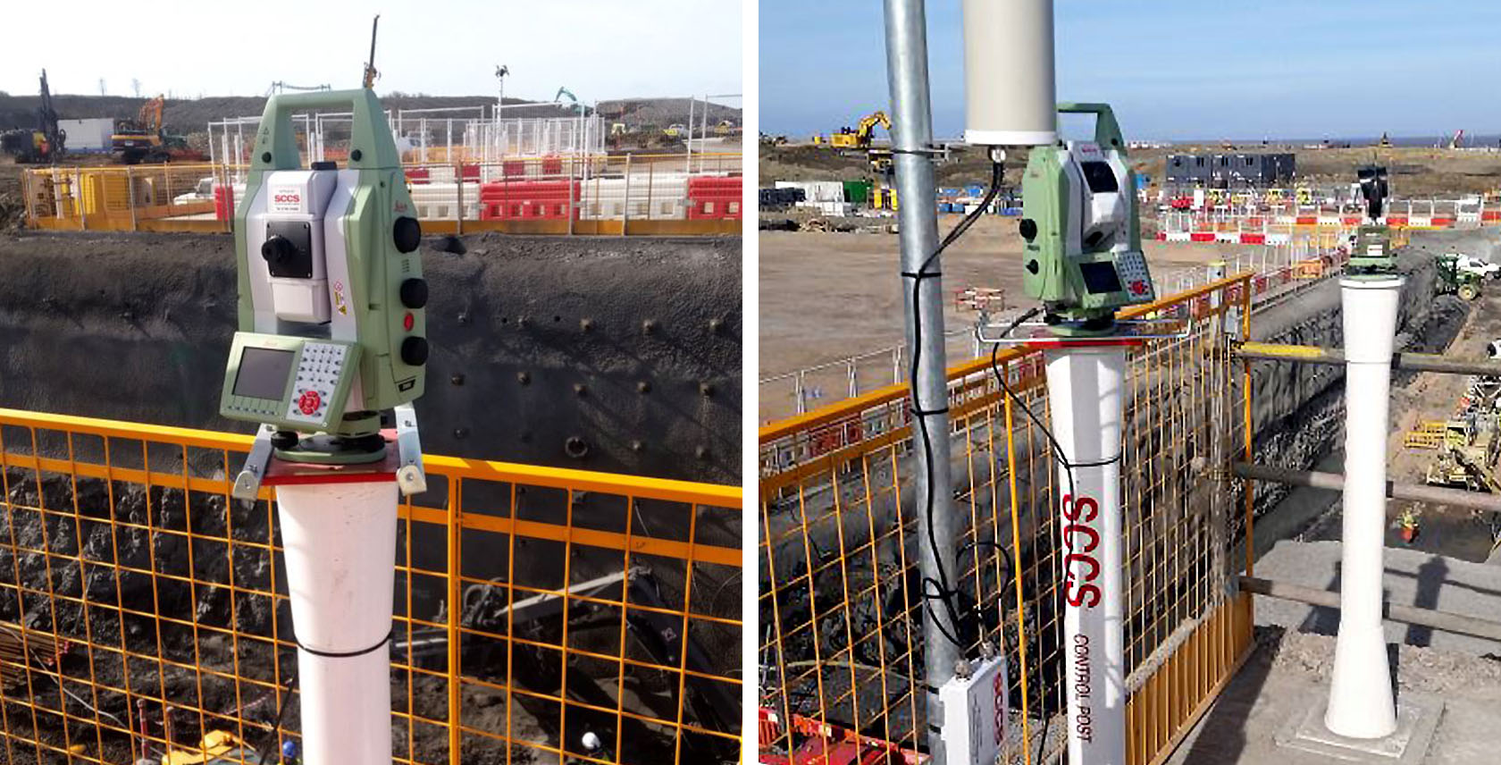
Image 1 (left): TM50 and mounting post, monitoring excavation
Image 2 (right): Typical setup of a monitoring system and control prism adjacent to excavation works
Selecting the right equipment
Deciding on a hardware and software provider is all about partnership. For the HPC project, this was a crucial factor. Only a firm, all-encompassing collaboration can satisfy the expected monitoring needs in terms of performance, durability, and reliability.
“Hinkley Point C is located adjacent to the Severn Estuary and is exposed to the Atlantic’s prevailing winds. I needed a product that could withstand these conditions, and I believed Leica as a respected and established brand was a safe selection to meet the project requirements,” said Ben Crossland, Senior Monitoring Surveyor at HPC.
After comparing diverse solutions, available on the market, HPC went for the collective power of Leica Geosystems’ and their distributor SCCS. The reasoning behind the decision was multi-layered – the equipment had to withstand the site’s conditions; the instruments had to perform flawlessly and enable surveyor control network integration. HPC required an “all-inclusive” package, including software, hardware, service and specialist support to meet HPC’s automated total station systems’ needs.
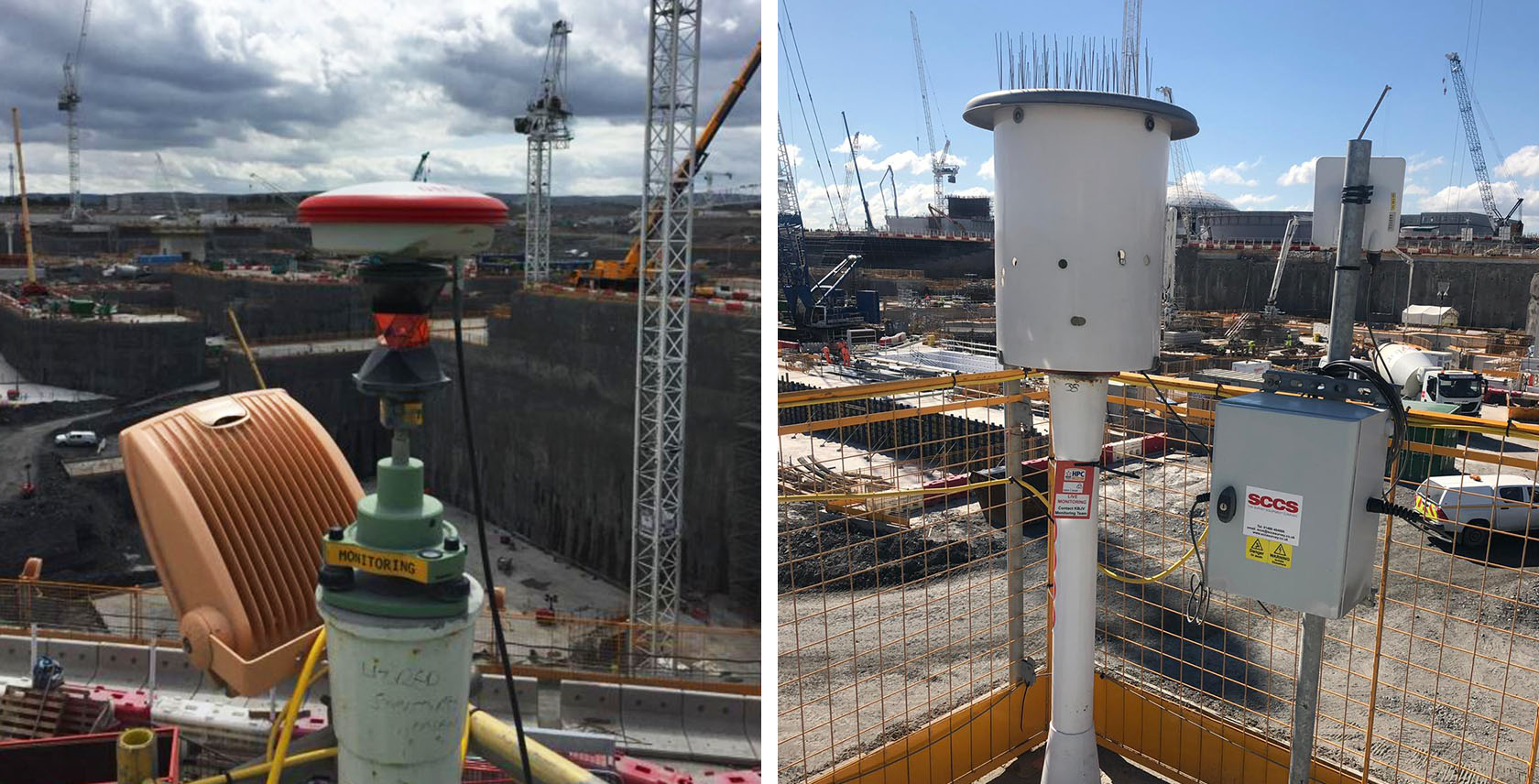
Image 3 (left): GNSS/360° prism survey control point
Image 4 (right): ATS with control box, WLAN radio and mounting post
The solution
Leica Nova TM50 monitoring total stations provided durable and precise instruments with the Leica GeoMoS monitoring software. Survey control measurements were processed by SCCS’s bespoke automatic adjustment script, which uses MicroSurvey Star*Net to adjust the ATS control network before every scheduled array slope monitoring measurement cycle. This system provided a fully integrated network, which would help remove the risk of false movement caused by survey control movement. The applied solution consists of the following components:
Software:
- 3x Leica GeoMoS Monitor software
- 1x Leica GNSS Spider Software
- 1x Leica Infinity survey software
- 1x Microsurvey STAR*NET adjustment software
- 1x SCCS SNASI bespoke automation scripting
Hardware:
- 40 x Leica Nova TM50 monitoring total stations
- 6 x Leica GMX910 GNSS smart antenna
- 25 x Leica GRZ122 prisms
- 2000 GMP104 and other monitoring prisms
- 2 x Leica Nova MS60 MultiStation
- 1 x Leica LS15 digital level
- 1 x Leica Nova TS60 total station
- 3 x PC’s with independent power and backup storage
- 46 x Communication and power enclosures with GSM/WLAN radios and solar panels
- 60 x TPS/GNSS/Prism mounting posts (1.2~1.8m tall) & protection enclosures for TPS
Leica LS15 digital level and Leica Nova TS60 robotic total station are used manually for survey control and manual monitoring verification checks to validate the ATS network was operating correctly. Together with these checks, HPC had six Leica GMX910 smart antennas controlled through Leica GNSS Spider software. One antenna sat on a permanent base station; the others were spread out within the work area. The antennas’ positions were co-located with Leica GRZ122 prisms to allow the ATS network to use the positions as fixed control. The integration of survey methods allowed real-time position checks to ensure relatively stable positions are not influenced by construction. In areas where prisms were obstructed, a Leica Nova MS60 MultiStation was used to scan the relevant zones. The data was then imported to Leica Infinity for cloud comparison. The MS60’s scanning ability was also used within GeoMoS when automated scanning was a preferred option due to impracticality of installing and maintaining prisms in dangerous areas.”
“We placed our GNSS systems differentially – one in a stable position (and fixed), the others in relatively stable positions, that are also considered pseudo-fixed. The potential for the positions to move was the reason for including GNSS as part of the solution. In this way, we could ensure unforeseen movement of fixed control positions that we deemed stable, was captured and addressed,” informed Crossland about the technical challenge. “We started with just prisms then realised our reference frame was flexing, so we asked advice from our supplier who helped solve the network stability problems we had by integrating GNSS”.
We needed to trust the equipment and the expert suppliers
“The main benefit of engaging in a supply partnership with Leica Geosystems and SCCS are the instruments themselves. This is where we trust the brand. Plus, it comes with great support,” Crossland summarised their experience. “You know what you paid for – the high quality is worth the investment. We are satisfied with how it works and are always eagerly expecting new advancements.”
Another decisive factor was the aspect of everything working together seamlessly. The interoperability is essential to set up a complex system as the HPC monitoring; thus, the GeoMoS platform combined these multiple data sources into a homogeneous monitoring system. Due to the project’s dynamic nature, the ATS system layout changed weekly. The company always strived to optimise the operation as new working zones open/close and improve the monitoring process to keep the workforce safe.
Customising the solution
Complex projects require the equipment/software provider to understand the customer’s needs thoroughly and always offer suggestions leading towards the optimal solution. The partnership went beyond the mere software/hardware support – with cooperation in operation plan optimisation, and custom builds related to the communication network (e.g., WLAN spanning the entire project).
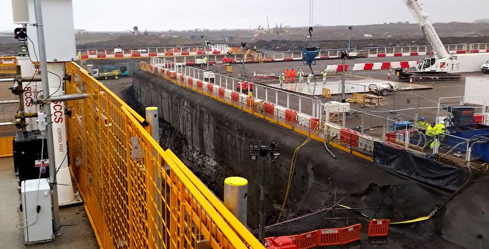
Image 5: Typical deep excavation into fractured rock held by sprayed concrete facades with rock anchor bolts, monitored by geotechnical instrumentation and arrays of geodetic prisms with an automated TM50 to ensure the safety of workers in and adjacent to deep excavations.
It’s all about the data
Every two hours, every day of the year, fully automatically, GeoMoS completes scheduled tasks to instruct the ATS system to collect a series of measurements to compute and update the ATS positions. Once updated, they then measured slope monitoring prisms and computed any deformation. The prism’s movement against a baseline is reported in GeoMoS and automatically sent to our client’s viewing portal MissionOS. Maxwell Geosystems Mission OS combines all HPC monitoring data, survey prism data, inclinometers, strain gauges, piezometers and extensometers. All monitoring data is reviewed through a daily section review group, where movement against construction and operational triggers is assessed. GMX910 data is received in GeoMoS on an hourly basis, which is averaged every 24 hours to enhance data stability, reliability and accuracy from the GNSS. The GMX910-processed average results are used in Star*Net integrated with the ATS network measurements to enable verification of all systems.
A recommendation
Once the slope monitoring project is completed, the stock instruments are assigned to other areas, especially those facing and combating line-of-sight issues, generally caused by construction programmes.
“I can easily recommend Leica Geosystems products. They are very transparent – I like to look into the GeoMoS system data, understand how the system operates, integrating the fine detail of observation and computation. The open access to raw data and log files was especially useful for a surveyor, so I understood how and why my system operated. I’ve used other products in the past which were supplied by 3rd parties and missed that same transparency where you could drill down into specifics of measurement and the data behind it,” Crossland concludes.
Interested in monitoring? Please feel free to read further case studies, showing how our customers use our solution to improve their monitoring workflow:


